
Why are ST Language Loops Considered Harmful?
The Structured Text (ST) language is among the languages of the IEC 61131 standard supported by PLC3000. Compared to other languages like Instruction List (IL), ST supports expressions with a higher level of abstraction. It notably provides loop statements. However, the use of loops is generally considered a poor practice when programming programmable logic controllers (PLCs).
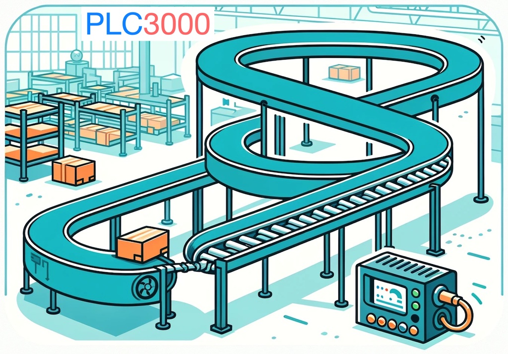
The recommendation to avoid loops in industrial automation is based on the structure of PLCs and their functioning. A PLC has multiple inputs/outputs that are connected to a system to automate or supervise. Inputs reflect the state of sensors, buttons, or switches. Outputs control devices such as actuators or indicators.
Program Execution Cycle: Sense, Plan, Act
A PLC runs a program that decides output values based on available inputs at each moment. This execution is performed in 3 steps:
- Sense : The PLC reads the state of the controlled system which leads to valued assigned to input variables.
- Plan : The program is then run from start to finish by the PLC.
- Act : Values stored in output variables are transmitted to the automated system.
These three steps are intrinsic to every PLC. They exist regardless of the programming language. They form the basic operation cycle of every PLC. This cycle is repeated indefinitely to produce the outputs based on inputs. The time spent by the PLC to execute a cycle must be small enough to quickly adjust outputs to changes observed on inputs.
Loops and their Impact on Automation
Since a program is run repeatedly by the PLC, we thus have an implicit main loop. Implementing a loop into a program is akin to nesting a second loop within the implicit main loop.
Loops repeat a given sequence of statements until some stop condition is reached. If we consider a FOR loop, it ends when the expected number of iterations has been completed. The time spent by the PLC in the FOR loop is all the more significant as the number of iterations is large. This delays the end of each cycle. During this time, the system can evolve without being accounted for by the PLC.
The same problem can occur with a WHILE or REPEAT loop. In the case of a WHILE, the PLC loops as long as some condition is true. This duration can extend if the condition remains true for a long time. Worse, if the condition depends on an input variable, the PLC remains indefinitely stuck in the loop. Indeed, inputs are refreshed only at the end of each cycle.
The problem observed with WHILE also applies to REPEAT statements. The PLC loops as long as the condition of the UNTIL statement is false. This loop can be infinite if the condition is a Boolean expression involving input variables. Remember, inputs are refreshed only at the end of each cycle.
Example of a Problem with Repeated Computations
Instead of using FOR, WHILE, or REPEAT loops, we recommend relying as much as possible on the PLC’s implicit main loop. IF conditions, counters, and timers provided by the PLC allow to cover a wide spectrum of repeated processes, without penalizing the cycle duration.
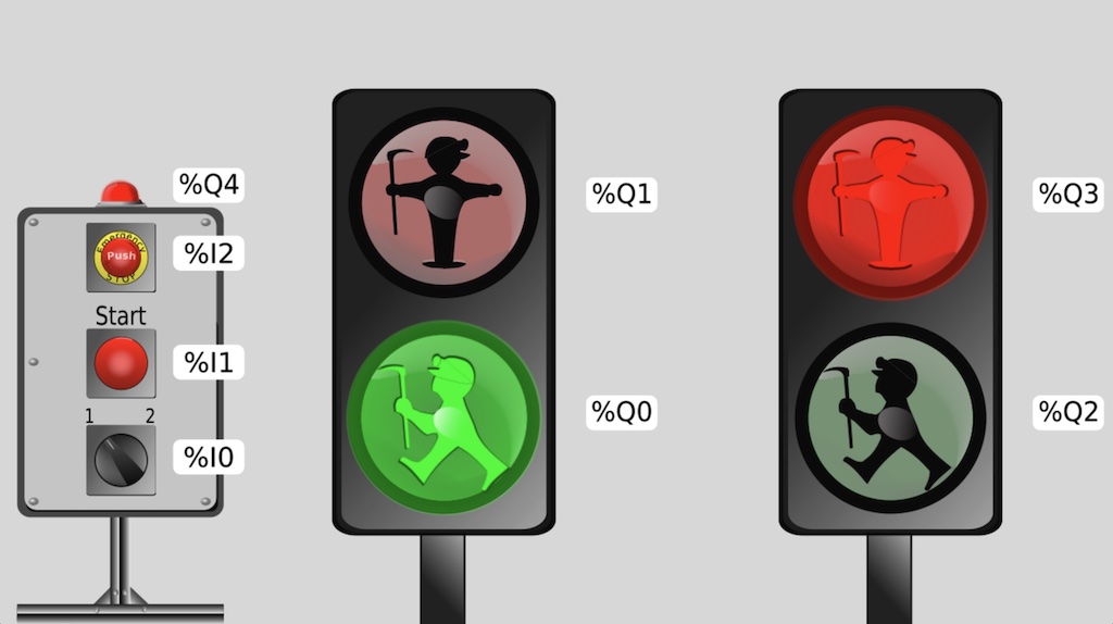
For illustration, consider the following problem based on an introductory PLC3000 bench shown on the figure above. Requirements are the following:
- The 2 lights should remain off until push button %I1 is pressed.
- Once %I1 is pressed, the two lights alternate from red to green 10 times every 500 milliseconds.
- Finally, the 2 lights are turned off.
One might mistakenly think that behavior (1) could be achieved with a WHILE or a REPEAT. However, using such statements would lead to an infinite loop. The PLC would get stuck because the value of %I1 read at the start of the cycle would be FALSE.
Similarly, the use of a FOR loop is not appropriate for implementing behavior (2). Since the outputs are only updated at the end of the cycle, we would not see any blinking.
Solution Based on the The Implicit Main Loop Only
In this section, we provide a solution in the ST language that addresses the above problem. It exclusively relies on the implicit main loop. This way, we avoid the inappropriate use of FOR, WHILE, and REPEAT loops.
Program with 3 States, 2 Timers and 1 Counter
Our program is organized as a 3 states automaton. The states are implemented using 3 integer variables:
readyState: The automaton waits for button %I1 to be pressed.redOnState: Red lights are turned on, and green lights are switched off.greenOnState: Green lights are turned on, and red lights are switched off.
A fourth variable currenteState of type INT denotes the current state. Two timers %T0 and %T1 allow controlling the duration of blinking states: redOnState and greenOnState. Counter %C0 tracks the number of d’iterations.
Upon launching the program, the above variables are initialized as shown in the code snippet below. This initialization is done only once since the the system bit %S1 which value is TRUE upon starting a program is automatically set to FALSE at the end of the first cycle.
PROGRAM alternateRedAndGreen10Times
VAR
	currentState, readyState, redOnState, greenOnState : INT;
END_VAR

(* Initialization *)
IF %S1 THEN
	%C0.PV := 10;
	%T0.PV := 5;
	%T0.TB := 100 ms;
	%T1.PV := 5;
	%T1.TB := 100 ms;
	readyState := 1;
	redOnState := 2;
	greenOnState := 3;
	currentState := readyState;
END_IF
Transitions
The second part of the program provided below defines transitions between states.
- While in state
readyState, if push button %I1 is pressed, we move to stateredOnStateto turn red lights on. - The automaton stays in state
redOnState, until output Q of timer %T0 is set to TRUE. This signals that the allocated time for the red lights has elapsed. The automaton transitions togreenOnState, which means turning off red lights and turning on the green ones. - We remain in the
greenOnStatestate until the output Q of timer %T1 becomes TRUE. This signals that the allocated time for green lights has then elapsed. Two disjoint transitions are then possible:- When output QU of counter %C0 is TRUE, the automaton goes back to the
readyState. Indeed, %C0 counts the red-green blinking. It fires QU when the count is 10. - Otherwise, if the targeted blinking counts is not reached, the automaton goes back to
redOnState. Thus, red lights are turned on.
- When output QU of counter %C0 is TRUE, the automaton goes back to the
(* Transitions *)
IF currentState = readyState AND %I1 THEN
	currentState := redOnState;
END_IF

IF currentState = redOnState AND %T0.Q THEN
	currentState := greenOnState;
END_IF

IF currentState = greenOnState AND %T1.Q THEN
 	IF %C0.QU THEN
		currentState := readyState;
	ELSE
		currentState := redOnState;
	END_IF
END_IF
Actions
We detail below the actions carried out in each state. We provide the portion of code for each state after giving the corresponding explanations.
Actions in readyState
- All lights should be off. Outputs %Q0 to %Q3 are set to FALSE.
- Besides, counter %C0 is reset to 0. This can be done by setting the counter’s input R to TRUE.
IF currentState = readyState THEN
	%Q0 := FALSE;
	%Q1 := FALSE;
	%Q2 := FALSE;
	%Q3 := FALSE;
	%C0.R := TRUE;
END_IF
Actions in redOnState
- Outputs %Q1 and %Q3 are set to TRUE to turn on the red lights.
- Outputs %Q0 and %Q2 are set to FALSE to ensure green lights are off. This step is important when transitioning from
greenOnStatetoredOnState. - Input IN of timer %T0 is set to TRUE to start the countdown of time allocated to the red lights.
- Input IN of timer %T1 is set to FALSE since the green lights should remain off as long as the red lights are on.
- Input R of counter %C0 is set to FALSE to enable counting blinking iterations.
- Last, input CU of counter %C0 is set to FALSE as the first step to a rising edge required to increment %C0 later in
greenOnState.
IF currentState = redOnState THEN
	%Q0 := FALSE;
	%Q1 := TRUE;
	%Q2 := FALSE;
	%Q3 := TRUE;
	%T0.IN := TRUE;
	%T1.IN := FALSE;
	%C0.R := FALSE;
	%C0.CU := FALSE;
END_IF
ActionsgreenOnState
- Outputs %Q1 and %Q3 are set to FALSE to ensure the red lights are off. This is important when transitioning from
greenOnStatetoredOnState. - Outputs %Q0 and %Q2 are set to TRUE to turn on the green lights.
- Input IN of timer %T0 is set to FALSE since the red lights remain off throughout this state.
- Input IN of timer %T1 is set to TRUE to start the countdown of time allocated to the green lights.
- Last, input CU of timer %C0 is set to TRUE. Thus, upon transitioning from
redOnStatetogreenOnState, we obtain a rising edge required to increment counter %C0 and keep track of the blinking count.
IF currentState = greenOnState THEN
	%Q0 := TRUE;
	%Q1 := FALSE;
	%Q2 := TRUE;
	%Q3 := FALSE;
	%T0.IN := FALSE;
	%T1.IN := TRUE;
	%C0.CU := TRUE;
END_IF

END_PROGRAM
Conclusion
The IEC 61131 standard allows using loops provided by the Structured Text (ST) programming language. However, although tempting, their use is not recommended. Indeed, PLCs rely all the time on an implicit main loop. The entire program is repeated cyclically.
A good PLC program must react as quickly as possible to changes in the inputs coming from the managed system. This is an essential condition for controlling a system adequately. However, FOR loops with many iterations can slow down cycles. Worse, REPEAT or WHILE statements can cause infinite loops if the conditions involve an input. In fact, the inputs/outputs are refreshed once per cycle.
Fortunately, it is possible to get rid of FOR, REPEAT and WHILE loops. We have illustrated how to do it in this article, through an example taken from the PLC3000 catalog. This example shows how to structure the program to exploit the PLC’s implicit loop in combination with counters and timers. The result is a program with a shorter cycle time which is therefore more responsive to changes in the controlled system.