
Principles of Sequential Logic
Sequential logic functions
Sequential logic functions are time-dependent. They define the state of output variables according to the combination of input variables, and also by the memorised state of one or more variables. They are often synthesised by flip-flops.
The interest of the sequential logic functions is demonstrated thanks to some examples.
Basics of sequential logic functions
The output %Q0 has to switch on when the button %I1 is pushed. It has to stay ON even if the button %I1 is released and until the button %I0 is pushed. It is supposed that pushing in the same time on %I0 and %I1 is forbidden. The corresponding truth table is:
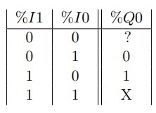
When none of the buttons %I0 and %I1 is pushed, it is not possible to specify the state of the output %Q0. To know this state, it is necessary to consider a memory and the time; i.e.memorize the state of the output at the previous time. The new truth table is
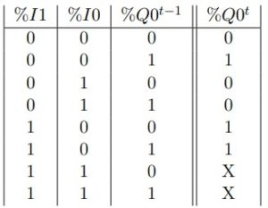
Without any input %I0 and %I1, the state of the output %Q0 remains the same. By simplifying this function, we obtain:
![]()
We use the memory bit %M0 to memorize the state of the output:![]()
The associated code is:
![]()
You can see the importance of time in these two lines of code, in particular the reading direction of these two lines (from top to bottom).
It is possible to use the properties of PLC (PLC3000), to achieve these functionalities easily. Several solutions exist and are presented below..
- Self-holding
Thanks to these properties, it is not necessary to use a memory (as before), but simply to code a self-holding.
%Q0=%I1+%Q0
That means the state of the output %Q0 at time t depends on the state of the output %Q0 at time t-1.
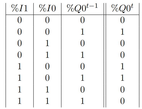
The drawback of self-holding is the output can not be switch off once it is ON. The activation of the output is true every time. It is necessary to add a new condition to switch off the output (with priority to OFF):
![]()
The truth table of this new function is:
- Forcing
Another possibility is the use of non-volatile memories with SET and RESET. The control SET leads to the forcing to 1 of a variable; RESET, the forcing to 0.
The drawback of forcing a variable is the variable stays at the state every time. Here also, it is necessary to add a new condition to switch off the output (with priority to OFF):
RESET %Q0 if %I0
Remark: Be careful, even if the use of forcing commands works, it is not recommended to use them to control power organs (press, cylinder, motor, etc.) for safety reasons. The use of volatile variables remains a priority.
Flip-flops design
Flip-flops are components dedicated to sequential systems. Some of them are detailled below.
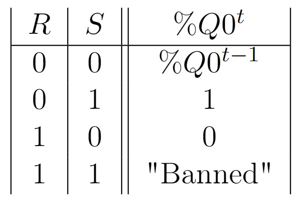
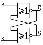
- Flip-flop RS
The RS is the most elementary flip-flop, using to store the value of a bit. Its truth table is given below.
 Even if this component already exists, it can be synthesised using elementary NOR logic gates:
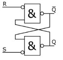
A second possibility consists in using the logic gates NAND as the following. Please note that inverse inputs are required.
- Flip-flop Timed RS
Flip-flops offer more interesting functionalities when they are synchronised to a clock signal $H$. A square periodic signal can be generated from two timers.
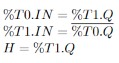
A timed flip-flop can be designed with NAND gates, according to:
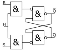
It is also possible to consider a Rising Edge (resp. falling) on signal H.
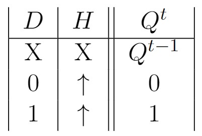
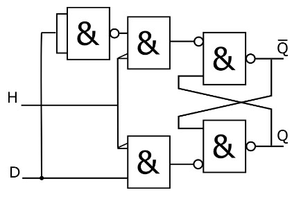
- Flip-flop D
The flip-flop D has one input and is synchronized on timer $H$. Its dynamic follow this truth table:
 Its design can be made with a RS flip-flop by inversing the two inputs S and R:
L’utilisation de plusieurs bascules D permet la synthèse de registres, compteurs, décompteurs.
The interest of using several D flip-flops is the design of registers, counters, decounters.
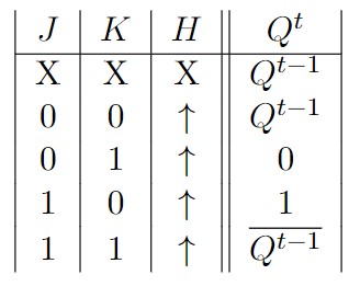
- Flip-flop JK
In synchronized mode, the flip-flop JK has two inputs and it is synchronized on timer H. Its dynamic follow this truth table.
Its design can be made with a RS flip-flop:
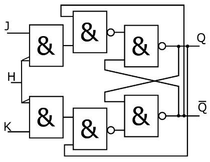
The use of several flip-flops JK leads to the design of registers, counters, decounters, state automata.