Automaton Properties
IEC 63111-1 compliant PLCs, such as the PLC3000 solution, are characterised by a cycle operation. A cycle is generally composed of 5 phases: 1. reading inputs, 2. scanning the program, 3. writing outputs, 4. communication services, 5. internal functions. The scanning of the program is always done from top to bottom and from left to right. This operation must be known, and can be used for the design of particular functions.
Unique Output Declaration
The sequence of the code lines is of crucial importance. By coding :
%Q4 = %I14,
%Q4 = %I15.
By checking the behaviour, you will notice that pressing %I14 has no effect on the output %Q4, because this line is contradicted by the second line; the code is executed from top to bottom. Hence, the state of %Q4 depends only on %I15.
In this case, it is necessary to code:
%Q4 = %I14 + %I15.
The purpose is to determine all the conditions allowing the unique activation of the output %Q4 (Unique Output Declaration).
Priority to OFF
It is possible to take advantage of this cycle to implement properties such as priority to OFF (Stop) (resp. ON – start). By coding:
SET %Q4 if %I4,
RESET %Q4 if %I14,
the priority is given to OFF because when the interruptor is switched ON %I14 and the button %I4 is pushed, the output %Q4 stays to 0.
Rising edge generation
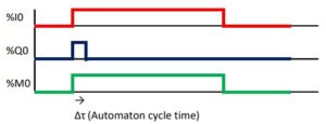
Rising and falling edges are specified in LADDER. However, it is possible to code by taking advantage to the automaton cycle. A memory bit is required:
%Q0 = %I0.%M0,
%M0 = %I0.
By pushing the button %I0, the output %Q0 goes to state 1 (only during a automaton time cycle) before coming back to 0. The rising edge generation on the pushing on %I0 has been codes and corresponds to %Q0.
The chronogram aims at illustrating this dynamics: